Top Z Distance vs Bottom Z Distance Explained: Slicer Mechanics and Interface Physics
 By Sophia Al-Mansoor
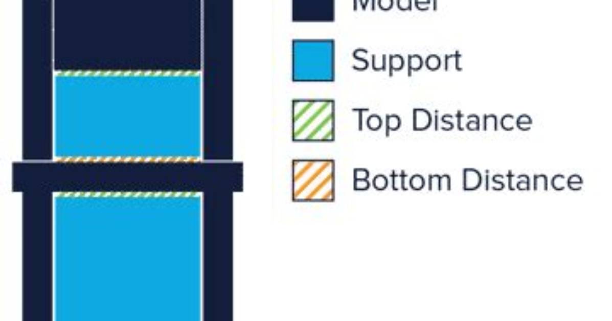
If dimensional accuracy and flawless visual quality are non-negotiable, adjusting Z distances in single-material prints represents an inevitable compromise. You either sacrifice overhang surface finish to ensure easy peeling, or you tighten the gap to improve flatness at the cost of strenuous post-processing.
Multi-material printing platforms, such as Bambu Lab's AMS, Prusa's MMU3, or dual-extrusion tool changers, bypass this geometric compromise entirely. By dedicating a separate spool to the interface layer, you can set both Top Z and Bottom Z distance to 0.00 mm.
[MODEL OVERHANG]
======================== <-- 0.00 mm Gap (Direct Contact)
[DENSE INTERFACE ROOF] <-- Incompatible material (e.g., PETG interface for PLA model)
[STANDARD BODY SUPPORT] <-- Primary PLA material
When you print a PLA model using a PETG support interface (or vice versa), the chemical incompatibility prevents the materials from molecularly bonding. The nozzle can pack the molten overhang flat against the dense interface roof without fusion.
When configuring zero-gap interfaces:
- Set Top Z distance to 0 mm.
- Set Bottom Z distance to 0 mm.
- Set Support interface layers to 2 or 3.
- Set Interface pattern spacing to 0 mm (solid 100% fill).
The resulting overhang surfaces match the smooth finish of prints produced directly on a textured PEI plate, completely eliminating interface scarring and layer droop.
Sophia analyzes international trade, startup ecosystems, retail transformation, and supply chain logistics for modern digital publications.
